Getting Started
In the section, we will first give you a quick overview on how to use the API documentation which is followed by a simple tutorial to get you all started with a long and exciting journey of learning and exploration.
Understanding API Documentation
The API documentation provides the understanding required to use a module for simulation and emulation purposes. Each module expects 2 set of arguments:
First set of arguments are expected at the time object creation (instantiation) called as Parameters of the module.
Second set of the arguments are passed while calling the object. These are called the Inputs.
If the module is configured correctly, it produce the one, multiple or no outputs. The type, size and shape of the Outputs is detailed in its API documentation.
Tip
The API documentation provides the users with access to Attributes and some additional methods (such as display functions) to get insights into the implementations.
Important
From a pythonic standpoint the __init__ arguments are addressed as Parameters and __call__ arguments are addressed as Inputs in the API documentation.
Hello World!
Let us get you started with your first script using 5G Toolkit. Its a very simple project which will perform following
\(\textcolor{blue}{\text{Cyclic Redundancy Check}}\)
\(\textcolor{blue}{\text{Symbol Mapping}}\)
\(\textcolor{blue}{\text{Add noise}}\)
The block diagram of the implementation is shown below:
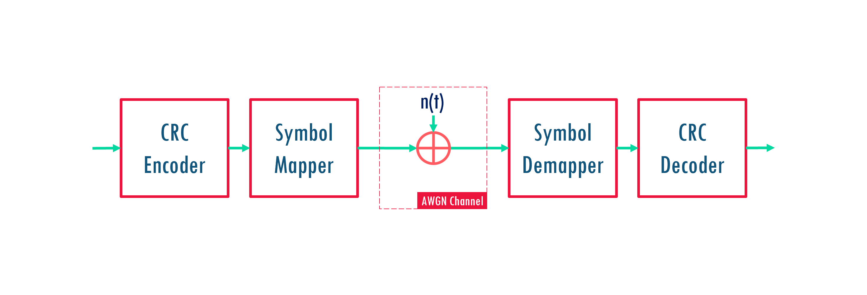
Note
CRC helps in error detection at the receiver. If CRC check fails, the receiver can request for retransmission of data.
Symbol Mapping converts bits into symbols for transmission.
Add noise introduce receiver noise to the transmitted signal to model AWGN channel.
Import Python Libraries
We will import NumPy, Matplotlib for linear algebra and plotting respectively.
import os
os.environ["CUDA_VISIBLE_DEVICES"] = "-1"
os.environ['TF_CPP_MIN_LOG_LEVEL'] = '3'
import numpy as np
%matplotlib widget
import matplotlib.pyplot as plt
Important
The following lines of code are used to disable the GPU if its not properly set up in your system. If GPU works well in your system, you can remove these lines.
import os
os.environ["CUDA_VISIBLE_DEVICES"] = "-1"
os.environ['TF_CPP_MIN_LOG_LEVEL'] = '3'
How to import 5G Toolkit Libraries
As understood from this diagram we require 5 modules for the whole implementation. These modules and the corresponding API are listed below:
CRC Encoder: toolkit5G.CRC.CRCEncoder
Symbol Mapper: toolkit5G.SymbolMapping.Mapper
AWGN Channel: toolkit5G.ChannelProcessing.AddNoise
Symbol Demapper: toolkit5G.SymbolMapping.Demapper
CRC Decoder: toolkit5G.CRC.CRCDecoder
These modules can be imported directly from the 5G Toolkit using the code shown below:
from toolkit5G.CRC import CRCEncoder
from toolkit5G.CRC import CRCDecoder
from toolkit5G.SymbolMapping import Mapper
from toolkit5G.SymbolMapping import Demapper
from toolkit5G.ChannelProcessing import AddNoise
Tip
It is recommended to import the required libraries alone. Aliasing is not mandatory.
Create Objects for all the Modules
The following code block will generate the objects to perform the designated operation for each module. As per CRC and Symbol Mapping documentation, we first create the CRCEncoder, CRCDecoder, Mapper, Demapper and AddNoise objects.
num_bits_per_symbol = 4
demapping_method    = "app"

crcEncoder    = CRCEncoder(crcType="CRC24C") # Create object of CRC Encoder
crcDecoder    = CRCDecoder("CRC24C")         # Create object of CRC Decoder
qamMapper     = Mapper("qam",num_bits_per_symbol)   # Create Mapper Object
qamDemapper   = Demapper(demapping_method = "app",
                         constellation_type="qam",
                         num_bits_per_symbol = num_bits_per_symbol,
                         hard_out = True)           # Create Demapper Object
awgn          = AddNoise()
Note
24 bit CRC is used for error detection.
16 QAM is used for symbol mapping
Log-MAP Symbol Demapper is configured to return hard outputs (0/1).
The symbol power will be 1 and power of noise added to the signal will be \(\frac{1}{\text{SNR}}\).
Generate Payload bits and Encode them
Generate a bit sequence randomly using randint() function from numpy.random library. Encode these bits using the crc encoder object.
numBlocks     = 10000
nBitsPerBlock = 384
bits          = np.random.randint(0, 2, size = (numBlocks,nBitsPerBlock)) # Bits to be Encoded
crcBits       = crcEncoder(bits)
Symbol Mapping the Encoded Bits
Perform 16 QAM on the bits. i.e map each group of 4 bits to a symbol using Mapper as shown below.
symbols = qamMapper(crcBits)
Pass through AWGN Channel
Create an AWGN Channel and pass the symbols through it. The AWGN channel will introduce the noise of power \(\frac{1}{\text{snr}}\) to the transmitted signal.
snr           = 70                      ## Signal to noise ratio
rxsymbols     = awgn(symbols, (1/snr))  ## Add AWGN noise with power = 1/SNR
Demapping the Symbols
The Demapper is used to convert the symbols back to either LLRs or bits based the type of output configured.
bitsEst = qamDemapper([np.complex64(rxsymbols), 1/snr]) # Demap the symbols into bits
Detect Error in the Blocks
The decoded bits is passed through CRC decoder to get the bits CRC removed bits and CRC check variable for each block.
rBits, checks = crcDecoder(bitsEst) ## Compute the CRC check and remove the CRC from the bits.
Note
If CRC check variable is True, then there is no error in the block. Otherwise, there is at-least one bit error in the block.
Compute Bit and Block Error Rate
The compare the transmitted bits with the received bits to compute the bit error rate. On the other hand, block error rate can be computed directly from CRC-check flag.
ber = np.mean(np.abs(bits-rBits)) # Compute the bit error/total number of bits
bler= 1-np.mean(checks)           # Compute the block error/total number of block

print("  Bit error rate = "+str(ber))
print("Block error rate = "+str(bler))
  Bit error rate = 6.71875e-05
Block error rate = 0.026599999999999957
Note
It is not practically possible to compute the bit error rate as transmitted bits are not known at the receiver. However, the receiver can compute the CRC check at the receiver without knowing the transmitted information which is used to computed the BLER.
Constellation Diagrams at the Tx and Rx
The following diagram compares the constellation diagram of transmitted and received symbols.
fig, ax = plt.subplots()
ax.set_aspect(True)

ax.scatter(np.real(rxsymbols), np.imag(rxsymbols), color = "red", marker=".", s=2)
ax.scatter(np.real(symbols), np.imag(symbols), color = "blue")

ax.set_xlabel("Real part $\mathfrak{R} \{x\}$")
ax.set_ylabel("Imaginary part $\mathfrak{I} \{x\}$")
ax.set_title("Contellation Diagram of transmitted and received symbols for 16-QAM")
ax.grid(which='both')
plt.show()

Link Level Simulation
The above procedure is repeated for different modulation order to analyse the SNR vs BER and BLER performance.
num_bits_per_symbol = 4
demapping_method    = "app"

crcEncoder    = CRCEncoder(crcType="CRC24C") # Create object of CRC Encoder
crcDecoder    = CRCDecoder("CRC24C")         # Create object of CRC Decoder
awgn          = AddNoise()


SNRdB    = np.linspace(0,25,10)
SNR      = 10**(SNRdB/10)
modOrder = np.array([2,4,6], dtype=np.int32)

ber   = np.zeros((modOrder.size, SNR.size))
bler  = np.zeros((modOrder.size, SNR.size))

numBlocks     = 10000
nBitsPerBlock = 384

i     = 0
j     = 0
for m in modOrder:
    qamMapper     = Mapper("qam",int(m))   # Create Mapper Object
    qamDemapper   = Demapper(demapping_method = "app",
                             constellation_type="qam",
                             num_bits_per_symbol = int(m),
                             hard_out = True)           # Create Demapper Object

    bits          = np.random.randint(0, 2, size = (numBlocks,nBitsPerBlock)) # Bits to be Encoded
    crcBits       = crcEncoder(bits)
    symbols       = qamMapper(crcBits)

    j = 0
    for snr in SNR:

        rxsymbols     = awgn(symbols, (1/snr))
        bitsEst       = qamDemapper([np.complex64(rxsymbols), np.float32(1/snr)])
        rBits, checks = crcDecoder(bitsEst)

        ber[i,j]      = np.mean(np.abs(bits-rBits))
        bler[i,j]     = 1-np.mean(checks)

        print("For modOrder = "+str(m)+" | snr = "+str(snr)+"  Bit error rate = "+str(ber[i,j]))
        print("For modOrder = "+str(m)+" | snr = "+str(snr)+"Block error rate = "+str(bler[i,j]))

        j = j + 1
    i = i + 1
Bit/Block Error Rate Performance
fig,ax = plt.subplots()
for i in np.arange(modOrder.size):
    ax.semilogy(SNRdB, ber[i], "-*")

ax.set_xlabel("SNR (dB)")
ax.set_ylabel("Bit error rate")
ax.set_title("BER vs SNR (dB) for different modulation order")
ax.set_xticks(SNRdB, minor=False);
ax.grid(which='both')
ax.legend(["QPSK","16QAM","64QAM"])
plt.show()

Resources and Scripts
Download the Getting started tutorial.
Thanks for reading this. Feel free to contact us for assistance. Post your question on the discussion forum, we will answer them as soon as possible.